Simple ATtiny13 Circuit
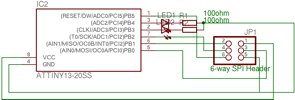
A two LED flasher is about as simple as it gets.
Note: Circuit and firmware now available
A simple LED flasher is a good project to get started with AVRs. This ATtiny13 based circuit alternately flashes 2 LEDs (or however you want them flashed).
There are a couple of simple SMD components which should cause no problems if you use flux on the board first, and good SMD techniques.
Here are images of the schematic and board:
These were produced using the free version of Cadsoft’s Eagle PCB program.
The actual schematic and board layout files, along with code to run the device will be provided shortly
*Update*
The circuit in Eagle format, and the firmware in C are now available here: led_flash.tar.gz
Wed, 18 Jan 2006 10:48 Posted in AVR Techniques
2 comments »
-
By hamidreza.206@gmail.com 02/07/2008 at 22h44
-
By Mauro Rodrgriguez 03/09/2009 at 04h24
I am using AVRStudio software to compile a program by ATtiny85 Then, I compile the simple program I need and It runs correctly but the problem is when I want to embbed it in ATtiny85 device. I have two doubts( at the moment),one of them is that I am using another device programmer. It is an universal programmer called “TopMax” with “MaxLoader” software, which has all ATtiny device in library.I don’t know if it is the problem because I embbed programs in 8051 AT family devices every day and problems don’t appear! . The other doubt is refered to Xtal frequency. I have understood It is set by default with internal clock and It is not necessary put an external Xtal or resonator.I will be forgeting something to set in my program but, as AVRStudio compiles It correctly I don’t realize where is the error.I attach .txt file with the simple program to show it. I hope you can understand I wanted to expalin to you and I beg your pardon about my bad english!


i want to sence temprature with attiny13 . i looking for a same sircuit and same c code